
In the manufacturing of complete sets of power equipment, high- and low-voltage switchgear, and transformers, the bending of copper and aluminum busbars constitutes a core process. To accommodate compact workshop layouts and complex routing requirements, designers often aim to make the bends in the busbars as compact as possible. However, in actual production, a “minimum distance” must be maintained between any two consecutive bends; if the design falls below this limit, the equipment will be unable to properly clamp the workpiece, potentially leading to severe deformation of the busbar.
Why must there be a "minimum distance" between two bends?
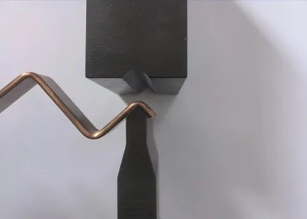
When a busbar machine bends a copper busbar, the bending dies (the concave and convex dies) require a sufficient contact area to secure the busbar; this creates a “clamping dead zone.”(Related article: Limitations of concave bending dies on Z-shaped bending)
- Die Interference: If the first bend is too close to the second bend, the already formed first bent section will collide with the bending table, ram, or safety guard during the second bending operation.
- Straight Section Clamping Requirements:A sufficiently long straight section must be maintained between two bends to enable the equipment’s clamping mechanism to firmly secure the copper busbar. If the busbar is not clamped securely, it will slip during the bending process, resulting in angular deviations or surface scratches.
So, what is the minimum distance between two bends?
The shortest distance between two bends typically refers to the distance Lmin between the centerlines of two consecutive bends; alternatively, it denotes the net length Smin of the intermediate straight section, which bears a direct and decisive proportional relationship to the die opening width Vwidth of the busbar bending lower die.
The width of the bottom die groove constitutes the most rigid physical constraint; during the busbar bending process, the busbar must span across the V-opening of the bottom die. Typically, the Vwidth of the bottom die used for bending busbars is approximately 8 to 10 times the thickness of the busbar. Simply put: the wider the bottom die groove Vwidth, the greater the minimum physical distance required between consecutive bends.
Vwidth=(8~10)t
Why does it depend on the slot width V?
Busbar bending is a typical “three-point bending” process. When the lower die groove width is V, the bending centerline—that is, the point where the punch presses down—is situated precisely at the exact center of the groove. In this configuration, the horizontal distance from the bending centerline to one edge of the lower die is exactly V/2.
When processing continuous bends (particularly reverse Z-bends):
1) Once the first bend is formed, the busbar takes the shape of an upward-standing or downward-hanging “corner.”
2) When processing the second bend, the busbar is advanced forward. If the distance between the two bends is too short, the “corner” formed by the first bend will become wedged directly against the edge of the lower die; consequently, the copper bar cannot sit flush against the surface of the lower die, preventing the machine from executing the downward stroke.
Therefore, half the width of the lower die groove—denoted as V/2 constitutes the primary physical limit for the minimum spacing between consecutive bends.
Quantitative Calculation Formula
Z-Bending — Most Heavily Influenced by Die Slot Width
If a busbar involves two bends in opposing directions, and the intermediate transition section is too short, the busbar will directly strike the side wall of the lower die during the bending operation. Typically, the minimum height (offset) required for a Z-bend is V/2 plus a certain safety margin (usually 3 to 5 mm).
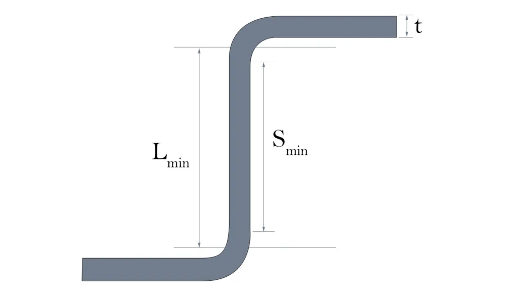
- Formula for the Net Length of the Intermediate Straight Section:
Smin=V/2+(3~5)mm
- Bending Centerline Axis Distance Formula(Considering Material Thickness T and Inner Bend Radius R):
Smin=V/2+R+T+(3~5)mm
U-Bending:
If two consecutive bends in a busbar are oriented in the same direction, a channel-like profile is formed. During the execution of the second bend, the raised edge resulting from the first bend must not make contact with the moving components of the upper die (tooling). Consequently, the minimum spacing required for a U-bend is primarily determined by the thickness and geometry of the upper die, as well as the half-width of the lower die’s V-groove.
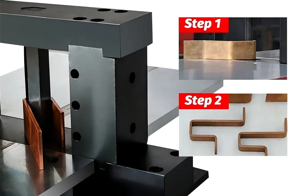
- The busbar rests upon the lower die, occupying half of the lower die’s V-groove width V/2 .
- The upper die tool must extend into the U-shaped recess; as the tool itself possesses a certain thickness, it occupies half of the upper die’s width A/2.
- The first flange—which has already been bent—also possesses its own inherent thickness (t).
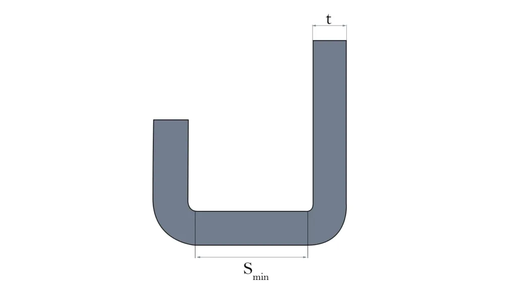
Smin=V/2+A/2+t
Case Description:
To validate the accuracy of the formula for calculating the minimum distance between consecutive bends in busbars, SUNSHINE conducted a series of practical laboratory tests using its in-house equipment—the SS-30-3CNC PRO busbar bending machine—specifically focusing on the Z-bend formula:
Smin=V/2+(3~5)mm
The test setup involved a busbar with a thickness of 10 mm and a width of 80 mm, paired with a bending die featuring a lower die groove width (V) of 80 mm (meaning the distance from the lower die edge to the center was 40 mm) and an upper die punch radius (R) of 5 mm, to perform a reverse Z-bend operation:
When the distance is less than V/2:
Adjust the back gauge positioning to correspond to a clear length of 25 mm for the intermediate straight section. After completing the first bend, advance the copper busbar in preparation for the second, reverse bend.
Phenomenon: As the upper die begins its downward stroke, the corner of the previously bent copper busbar slams violently against the edge of the lower die’s female die. As the pressure intensifies, the busbar fails to enter the V-groove smoothly; consequently, the edge of the lower die subjects the busbar to severe compressive deformation. Due to excessive resistance, the equipment triggers its overload protection system and shuts down. The surface of the workpiece exhibits deep indentations and gouges reaching up to 2 mm in depth, and the intended bend angle fails to form at all.
When the distance is exactly V/2:
The clear length of the central straight section is adjusted to be exactly equal to 40 mm (the value of V/2).
Observation: During the formation of the second bend, the first bend—already formed—slides into the lower die opening, almost “grazing” against its edge. Due to the complete absence of any safety margin, the moment the bending operation initiates, the minute elongation of the material resulting from tensile stress on the outer radius causes severe friction between the copper busbar and the edge of the lower die. Although a Z-bend was successfully formed, the angle of the first bend was “pulled off-axis” and distorted by 1.5°; furthermore, the central straight section exhibited distinct signs of metal peeling caused by scraping against the edge of the lower die.
After adding a safety margin of 3–5 mm:
Strictly adhering to the safety value calculated via the prescribed formula, the net length of the straight section was set to 45 mm (specifically, the safety clearance V/2+5mm).
Observation: During the machining process, a visible safety clearance of approximately 4 mm was maintained between the first bend and the edge of the lower die. The copper busbar rested smoothly against the surface of the lower die, exhibiting no signs of slippage or lifting. The bending angle accuracy achieved a tolerance of ±0.3°, the surface of the copper busbar remained smooth and free of scratches, and the transition between the two curved sections was exceptionally fluid and natural.
Conclusion: This verifies that V/2 is indeed an insurmountable mechanical interference limit. However, V/2 alone can only guarantee “no machine collision,” but not “processing quality.” A safety margin must be introduced.
The minimum distance for continuous bending is not only a geometric problem, but also a comprehensive reflection of the equipment manufacturing process. Choosing a busbar machine with high-precision electrical control and optimized mold design can make your electrical layout more compact and aesthetically pleasing.
As a leading global supplier of busbar processing solutions, SUNSHINE is committed to providing high-precision CNC busbar punching, shearing, and bending equipment. Furthermore, it offers customized molds and software support to address extreme process challenges such as “ultra-short straight section bending” and “multi-stage continuous twisting bending.” If you are facing spatial layout challenges in copper busbar processing, please contact the SUNSHINE technical expert team for a free copper busbar bending process assessment and prototyping solution.